- Location
- Portland, OR
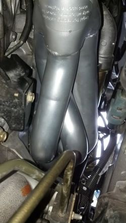
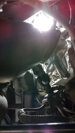
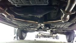
This is a guide to installing headers on a 1st gen FX35. Mine are made by Stillen but the steps involved apply to any headers. This install is not for the faint of heart. If you don't have a significant set of tools and the better part of a weekend to devote to the project, I'd suggest having it done by professionals. That said, it's not so much a matter of difficulty as it is patience, physical and mental flexibility, and having a wide assortment of tools at your disposal.
This guide assumes a certain level of mechanical aptitude, and as such certain steps and details are assumed and omitted for clarity. Again, if after reading this guide you are not 100% confident that you can pull this job off safely, take it to a pro.
Torque specs:
Exhaust manifold nuts = 22 ft/lbs
Oxygen sensors (all) = 33 ft/lbs
Manifold to cat bolts = 46 ft/lbs
Cat to Y-pipe bolts = 39 ft/lbs
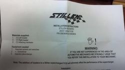
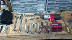
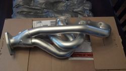
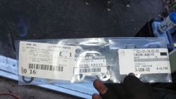
Step 1) Assemble tools and materials. The first picture below is of the instructions Stillen sends with their headers. Note the "Equipment needed" section, have a nice chuckle, and then crumple them up and throw them away. They are confusing and borderline worthless. The second pic shows the tools that I ended up using. The third pic shows the new headers. The fourth is the new exhaust manifold gaskets.
Stillen instructions:
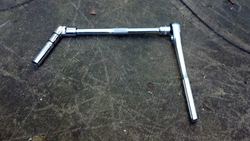
Tools used: (My 3/8" drive 14mm deep socket is not pictured here but was instrumental in the removal and installation of every single exhaust manifold nut. Other tools not pictured here are: ramps or jack stands, tire chocks, a crawler, and a tool tray to hang out under the car with you for hours at a time.)
New Stillen headers:
Exhaust manifold gaskets:
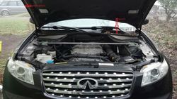
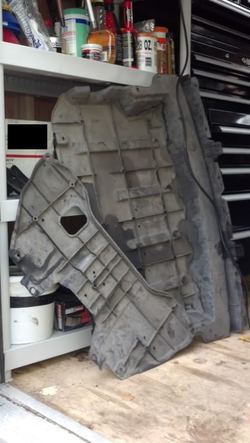
Step 2: Prepare vehicle. You'll definitely want the front up on ramps or jack stands. Raising the back wheels makes things more comfortable but is not entirely necessary. You'll also want to remove both lower engine covers and open the hood.
FX in serviceable position:
Engine covers removed:
Step 3: Disconnect negative battery terminal. I skipped this one and paid the price in the form of a $64 fuse block on the positive battery terminal. :.frown:
Step 4: Remove intake. Remove the intake up to the throttle body. It's a good idea to plug the TB opening with a rag or some paper towels to prevent contamination during the course of your work.
Intake removed:
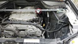
At this point you'll be able to clearly see the heat shield on the driver's side. (outlined in red):
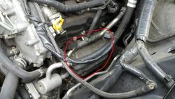
The passenger shields are a little less accessible and thus, more awkwardly removed:
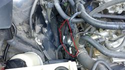
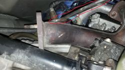
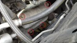
Step 5: Remove heat shields. Each heat shield is bolted to it's respective exhaust manifold with four bolts (outlined in red). Shown below is the driver's side. The passenger's side is mirrored. Nothing tricky about this one - a ratchet and socket fit just fine and both shields come out through the bottom.
Driver's side heat shield bolt locations:
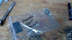
Bag it 'n' tag it!
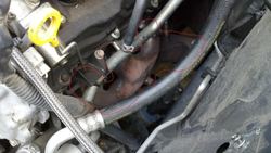
OEM manifolds revealed:
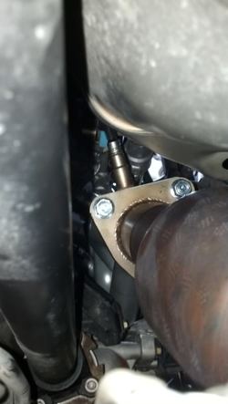
Step 6: Remove catalytic converters. This is a multi-step process within itself, but is very straightforward. There is one manifold-to-cat nut on each side that has to be removed from the top, then the other two on the manifold-to-cat flange, along with the two cat-to-Y-pipe bolts, can be removed from under the vehicle. *If you have stock cats, you'll have an extra connection (cat to transmission) to remove on each side.
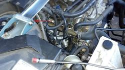
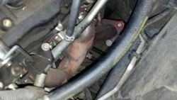
Manifold-to-cat nut to be removed from above (outlined in red):
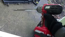
1/2" drive impact wrench with 20" extension, 3/8" step down adapter, and 14mm deep socket. Sweet fingerless gloves to combat 32 degree weather and any unexpected road warriors should they happen to show up lookin' for trouble:
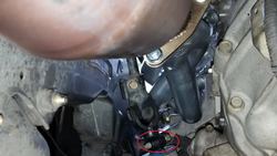
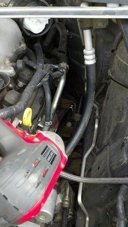
Nut removal. Note 14mm box wrench (outlined in red) on the bottom side of the flange:
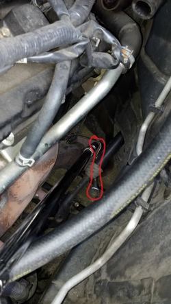
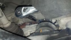
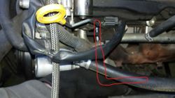
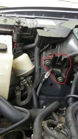
In order to reach the first nut on the passenger side, you'll need to unclip the fluid reservoir and push it aside. No need to disconnect or drain anything - the hoses will reach. (Clip outlined in red):
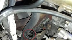
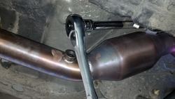
The two remaining nuts on each side are accessible from the bottom with a combination of wrenches and extensions that will vary depending on your installed equipment:
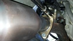
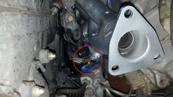
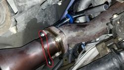
Note the box wrench (outlined in red) on the back side of the flange:
Once the cats are disconnected from the manifolds and Y-Pipe, rotate them slightly to easily reach and remove the oxygen sensors (one on each side). Once they are completely free, pull them out the bottom.
Take a break. That was the easy part.
This guide assumes a certain level of mechanical aptitude, and as such certain steps and details are assumed and omitted for clarity. Again, if after reading this guide you are not 100% confident that you can pull this job off safely, take it to a pro.
Torque specs:
Exhaust manifold nuts = 22 ft/lbs
Oxygen sensors (all) = 33 ft/lbs
Manifold to cat bolts = 46 ft/lbs
Cat to Y-pipe bolts = 39 ft/lbs
Step 1) Assemble tools and materials. The first picture below is of the instructions Stillen sends with their headers. Note the "Equipment needed" section, have a nice chuckle, and then crumple them up and throw them away. They are confusing and borderline worthless. The second pic shows the tools that I ended up using. The third pic shows the new headers. The fourth is the new exhaust manifold gaskets.
Stillen instructions:
Tools used: (My 3/8" drive 14mm deep socket is not pictured here but was instrumental in the removal and installation of every single exhaust manifold nut. Other tools not pictured here are: ramps or jack stands, tire chocks, a crawler, and a tool tray to hang out under the car with you for hours at a time.)
New Stillen headers:
Exhaust manifold gaskets:
Step 2: Prepare vehicle. You'll definitely want the front up on ramps or jack stands. Raising the back wheels makes things more comfortable but is not entirely necessary. You'll also want to remove both lower engine covers and open the hood.
FX in serviceable position:
Engine covers removed:
Step 3: Disconnect negative battery terminal. I skipped this one and paid the price in the form of a $64 fuse block on the positive battery terminal. :.frown:
Step 4: Remove intake. Remove the intake up to the throttle body. It's a good idea to plug the TB opening with a rag or some paper towels to prevent contamination during the course of your work.
Intake removed:
At this point you'll be able to clearly see the heat shield on the driver's side. (outlined in red):
The passenger shields are a little less accessible and thus, more awkwardly removed:
Step 5: Remove heat shields. Each heat shield is bolted to it's respective exhaust manifold with four bolts (outlined in red). Shown below is the driver's side. The passenger's side is mirrored. Nothing tricky about this one - a ratchet and socket fit just fine and both shields come out through the bottom.
Driver's side heat shield bolt locations:
Bag it 'n' tag it!
OEM manifolds revealed:
Step 6: Remove catalytic converters. This is a multi-step process within itself, but is very straightforward. There is one manifold-to-cat nut on each side that has to be removed from the top, then the other two on the manifold-to-cat flange, along with the two cat-to-Y-pipe bolts, can be removed from under the vehicle. *If you have stock cats, you'll have an extra connection (cat to transmission) to remove on each side.
Manifold-to-cat nut to be removed from above (outlined in red):
1/2" drive impact wrench with 20" extension, 3/8" step down adapter, and 14mm deep socket. Sweet fingerless gloves to combat 32 degree weather and any unexpected road warriors should they happen to show up lookin' for trouble:
Nut removal. Note 14mm box wrench (outlined in red) on the bottom side of the flange:
In order to reach the first nut on the passenger side, you'll need to unclip the fluid reservoir and push it aside. No need to disconnect or drain anything - the hoses will reach. (Clip outlined in red):
The two remaining nuts on each side are accessible from the bottom with a combination of wrenches and extensions that will vary depending on your installed equipment:
Note the box wrench (outlined in red) on the back side of the flange:
Once the cats are disconnected from the manifolds and Y-Pipe, rotate them slightly to easily reach and remove the oxygen sensors (one on each side). Once they are completely free, pull them out the bottom.
Take a break. That was the easy part.
Last edited: