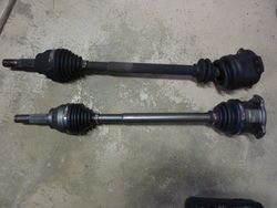
How to change the left/driver side front drive shaft

la_fx35

Staff
Moderator
Location
Chicago
Car
2017 QX70S
Name
Andy
Remove and install the left drive shaft
1) Lift both front wheels with jack and support both side with jack stand.
2) Remove the driver side front wheel.
3) Remove the wheel sensor harness from the clips on the strut assembly.
4) Remove the brake line lock plate and then remove the brake line from the strut assembly.
5) Remove the cotter pin from the axle.
6) Remove the 32 mm axle nut with power tool or break bar with jack handle bar or pipe slip onto the end of the break bar for leverage.
7) Remove the two 22 mm bolts to separates the knuckle from the strut assembly.
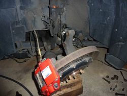
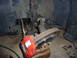
8) Separate the knuckle from the strut assembly. Be sure to use wood block to support the knuckle assembly.
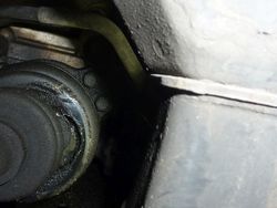
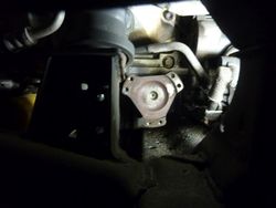
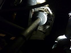
9) Slide the outer end drive shaft off the hub.
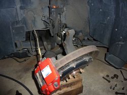
P1080675_zps165cd324.jpg

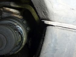
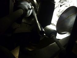
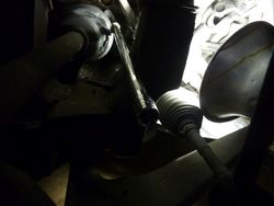
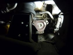
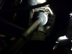
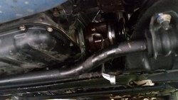
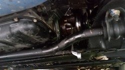
10) Remove the six 12 mm bolts of the final drive assembly to separate the drive shaft from the final drive assembly.
Turn drive shaft to position the bolts for ease of access.
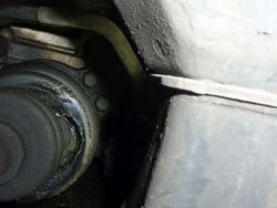
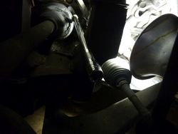
P1080671_zps05f4e73a.jpg
P1080678_zps5b99123d.jpg

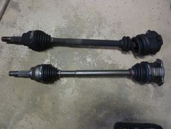
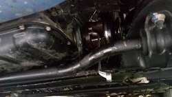
11) Once the bolts are removed, just gab the shaft and give it a little tuck to separate it from the final drive assembly.
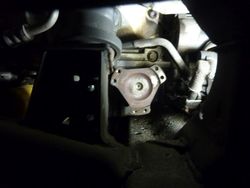
P1080684_zps69bcd0b8.jpg
P1080679_zps0113a88a.jpg

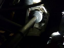
12) Install the new drive shaft and tighten the six 12 mm bolts to 33 ft-lb
P1080687_zpsb20316a7.jpg

13) Slide the outer end of the drive shaft back onto the hub.

14) Reassemble the knuckle back onto the strut assembly and tighten the two 22 mm bolts to 134 ft-lb.

15) Reassemble the brake line and wheel sensor harness back onto the strut assembly.

16) Re-install the 32 mm axle nut and tighten it down to 203 ft-lb.

17) Re-install the cotter pin.

18) Re-install the wheel, lower the car and test drive.


Remove and install the right drive shaft
Here is the DIY link to the right/passenger side front drive shaft.
FX45 - How to change the right/passenger side front drive shaft

handyandy_thejackchanofmechanics-eyes_zps290dfec4.png
 

Attachments

  • P1080675_zps165cd324.jpg
    P1080675_zps165cd324.jpg
    145.7 KB · Views: 293
  • P1080675_zps165cd324.jpg
    P1080675_zps165cd324.jpg
    145.7 KB · Views: 273
  • P1080671_zps05f4e73a.jpg
    P1080671_zps05f4e73a.jpg
    124.3 KB · Views: 291
  • P1080671_zps05f4e73a.jpg
    P1080671_zps05f4e73a.jpg
    124.3 KB · Views: 297
  • P1080678_zps5b99123d.jpg
    P1080678_zps5b99123d.jpg
    87.8 KB · Views: 301
  • P1080678_zps5b99123d.jpg
    P1080678_zps5b99123d.jpg
    87.8 KB · Views: 315
  • P1080679_zps0113a88a.jpg
    P1080679_zps0113a88a.jpg
    141.7 KB · Views: 304
  • P1080684_zps69bcd0b8.jpg
    P1080684_zps69bcd0b8.jpg
    87.1 KB · Views: 286
  • P1080684_zps69bcd0b8.jpg
    P1080684_zps69bcd0b8.jpg
    87.1 KB · Views: 361
  • P1080687_zpsb20316a7.jpg
    P1080687_zpsb20316a7.jpg
    84.3 KB · Views: 315
  • P1080679_zps0113a88a.jpg
    P1080679_zps0113a88a.jpg
    141.7 KB · Views: 297
  • P1080687_zpsb20316a7.jpg
    P1080687_zpsb20316a7.jpg
    84.3 KB · Views: 314
  • handyandy_thejackchanofmechanics-eyes_zps290dfec4.png
    handyandy_thejackchanofmechanics-eyes_zps290dfec4.png
    5.1 KB · Views: 220
  • handyandy_thejackchanofmechanics-eyes_zps290dfec4.png
    handyandy_thejackchanofmechanics-eyes_zps290dfec4.png
    5.3 KB · Views: 186
Last edited:
Thanks for pointing me to this, figured you'd always have a DIY handy for just about anything. Any specific tools needed for this outside of the usual? Didn't know if you needed specific extensions to get to the 6 12mm bolts. They're a little ways in there. I have a pretty robust set of tools, just want to prevent having to drive down to the store halfway through the job.
 
No special tools needed. just a couple various length extension will do. I think all that I use was a 12" extension.
 
So I just did this today and I think there were a few changes somewhere between your model year and mine. I was expecting a quick 90 minute job if that; it ended up taking 5 hours with fruitless trips to Pep Boys. As it turns out, the 6 bolts on my '07 that connect the driveshaft to the differential are not 12mm. They're 10mm spline drive, I tried my 3/8" drive socket and it fit, but I couldn't get an extension on it. No big deal, go to the store and get a 1/4 drive 10mm socket. Get home and realize it doesn't fit, it's a 6 point socket and the bolt is a spline. Go back to the store and get a 12 point socket; it fits, but there is no way an extension fits on there even with the smaller 1/4" drive. In your pic, there is enough room to get a socket and extension on, but on mine, the recess is too small and the part the boot clamps to sticks out too far. No combination of universal joint, wobble joint, or low profile driver will get in there.

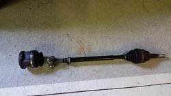
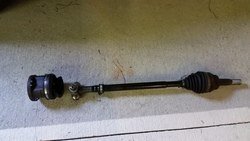
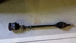
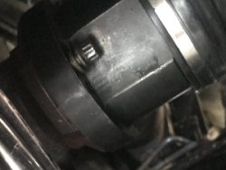
For those of you with a newer model, you have to drop the belly pan and get a wrench on there. The wrench has to be low profile, I couldn't even use a ratcheting wrench, the head was too big. So I had to take those bolts out 1/4 turn at a time with a fixed head wrench. Took 30 minutes since each bolt took something like 55 1/4 turns and I had to keep repositioning the wrench, no clearance with sway bar. Could only use an offset box wrench - in pic. You can see how the boot blocks using extensions. Also notice that the drive shaft is no longer attached even though I haven't pulled the 6 bolts. As soon as I lowered it after pulling it from the hub, it fell out, the bearings were so loose nothing held it in. Annoying since I had to put it back in to rotate it to get to all the bolts. This does resolve the clicking I was getting at low speeds before, the bearings were shot (drove 100 miles today and no clicking so it was the drive shaft).

20150801_132840.jpg

Installing the new CV took 20 minutes; new part had enough clearance to use a socket and extensions for the 6 bolts.
 

Attachments

  • 20150801_132840.jpg
    20150801_132840.jpg
    109 KB · Views: 160
  • 20150801_132840.jpg
    20150801_132840.jpg
    109 KB · Views: 167
Last edited:
Yeah, halfway through I considered just setting the car on fire, I was so annoyed. The good thing is that for anyone else who is thinking about doing this, it's easy enough to just look at the part before removing to make sure you have the right tools. If I had known I didn't have clearance, I could have shaved over an hour from the job instead of trying every combination of extension known to man. It's weird because the replacement looks pretty much like yours except the end is circular and isn't cut out between the bolts. The overall length was the same as OEM, but the shaft itself was shorter and the bearing housing was slightly longer. I'll take a pic tomorrow to show how short the bearing housing is on my OEM one and maybe people can see which year they started using that style. Pretty sure the parts are interchangeable since most places sold them for 03-08.
 
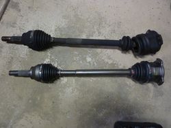
20150803_144451.jpg

Here's the drive shaft after removal, you can sort of see how short the area between the bolts and boot are and how little clearance there is. It separated like this as soon as I pulled it from the hub. As soon as I put it down and there was weight on the bearings, it just fell out since there was no boot holding it in and the bearings were really loose and had a ton of play.
 

Attachments

  • 20150803_144451.jpg
    20150803_144451.jpg
    100.6 KB · Views: 205
  • 20150803_144451.jpg
    20150803_144451.jpg
    100.6 KB · Views: 168
Ha, what a pain that is. I know for certain the 03 - 05 FX35 & FX45 look just like my pictures. I can see the hex head of the bolts by looking from through the wheel well hub area. On the 07 FX35 off shadow's you cannot see the head of the bolt from the wheel well hub area due to bolts are in a recessed behind the clamp area.
 
Yeah, I see how yours sticks out so there is easier access. The replacement I installed looks like mine with the bolts recessed, but has a longer bearing housing so you can still get a socket and extension on it.
 
Just did this yesterday to the right side of my FX, hope it all goes well now. This DIY helped out some. :good:
 
May I ask why would you replace it? (I understand if its broken, etc). Is it an upgrade of some sort to better quality parts?
 
Yeah it broke all the grease came out so to replace the boot I'd have to pull out the whole axel. So I opted to change it completely. To pull it out it was sort of similar to the drivers side in that I had to remove 5 screws in order to get more play to pull out the axel you can see them in the picture with the new axel installed. Don't know for sure if that was necessary but it really helped me out in doing it.

Sent from my SM-N920V
 
I just did my axles on my 2003 fx35. I would recommend that to loosen the axle nut that you take off your wheel, take out the cotter pin, take off your center cap from you wheel and then put the wheel back on and then lower the car to the ground so that all torque you need to take the axle bolt off goes into the bolt - otherwise you will end up just spinning the axle.

I have a general question... when you take out the passenger side axle - was your retainer clip left in the transfer case or did it come out with the axle... and if it wsa left in the case did you remove it and put a new one on the shaft or just reuse the one left in the transfer case?
 
I replace my BIL's 03 FX35 driver side today. What PIA that was. As shadow have shown up front that the six 10 mm spine bolt are recessed that you have to use the offset box wrench with only 1/4 turn at a time. On top of that the matting surface on the new shaft has a beveled lip instead of a straight edge (90 degree) lip that the shaft shift if you try tighten down on one of the six bolts too much that it binds the other four bolts. So I have tighten the six bolts down evenly; which mean I can have to constantly spin the wheel so that the bolt can be accessed from front of the car (car jacked up with belly pan removed).
 
I replace my BIL's 03 FX35 driver side today. What PIA that was. As shadow have shown up front that the six 10 mm spine bolt are recessed that you have to use the offset box wrench with only 1/4 turn at a time. On top of that the matting surface on the new shaft has a beveled lip instead of a straight edge (90 degree) lip that the shaft shift if you try tighten down on one of the six bolts too much that it binds the other four bolts. So I have tighten the six bolts down evenly; which mean I can have to constantly spin the wheel so that the bolt can be accessed from front of the car (car jacked up with belly pan removed).

Did you have to use a hammer or anything to tap the right inner joint housing into the left inner join? I'm currenlty working on mine now and I'm having a hard time getting it to fit flesh on there and on top of that. I can't seem to get my wrench on the bolt as the bolt seems to be too close to the cv joint housing.
 
You shouldn't have to tap them together. They should mate up against each other. Sounds like your had the recessed bolt that you can't see the hex of the bolt looking straight at it. So an offset box wrench with a 1/4 turn at a time on each bolt.
 
You shouldn't have to tap them together. They should mate up against each other. Sounds like your had the recessed bolt that you can't see the hex of the bolt looking straight at it. So an offset box wrench with a 1/4 turn at a time on each bolt.


I think the problem with mine is that there are some rust on the inner left joint. As of now there’s a small gap between the inner left and the inner right cv joint
 

Attachments

  • C30ECF15-9DDA-4704-9DFB-AF0A677C1816.jpeg
    C30ECF15-9DDA-4704-9DFB-AF0A677C1816.jpeg
    128.4 KB · Views: 168
Back
Top